Showing posts with label Projects. Show all posts

Sunday, December 30, 2018

LED Google Cloud

While I was at school and later at university, many of my friends were building all kinds of home made electronics: radios, light systems, etc. For some reason I was not interested in soldering and electronics and gravitated to software at one extreme and to woodworking and other things made out of metal, bricks, etc. However my most recent fun project required LED lighting and forced me to learn soldering and basic circuit design, which I have enjoyed very much! Here is how it came about.

For my 20% project of 2018 at Google I have created a self driving car (details at cloudderby.io). We now use these cars across the world to run customer facing hackathons to teach Google Cloud skills to clients. To built enough cars for those hackathons I had to purchase 20 car kits at the Five Dollar Store. One of the things that was not used for the final car, were the cheap plastic wheels from those kits - we replaced them with rubber wheels for better traction. Hence I had 80 plastic wheels sitting in a box. There is no way I am putting 80 perfectly good wheels into recycling! Hence I decided to build a Google Cloud sign from plywood and used wheels as decoration:

This came out nice, but was a little dark, so I decided to add LED lights to match the colors of the official Google logo:
Initially I thought to buy a pre-lit LED light and insert it into these letters, but that seemed like a flawed approach for several reasons:
  1. Pre-lit lights are bulky;
  2. They do not have exact number of LEDs that I need and there will be extra lights to be hidden behind the sign;
  3. They do not have right mix of colors (I need 4 colors for letters);
  4. If pre-lit light breaks, it may be hard to repair;
  5. It is not much fun to use ready-made light as I wont learn much.
Hence I decided to build my own LED light. It turns out LEDs are super cheap in bulk. I bought 450 LEDs for $13 on Amazon (aka single LED cost is about 3 cents). When it came to designing a circuit, it turns out you can't simply string together those lights and expect it to work. One has to consider the following factors:
  1. Total number of wheels (aka LEDs) in my design is 44;
  2. Power adapter - I selected 12V DC, 1A adapter that plugs into a standard wall outlet;
  3. Voltage drop on each LED varies from 2V to 3.3V (depending on the color - in my case 2V for yellow and red, 3V for green and blue). This means that serial circuit for 44 LEDs will require a lot more than 12V, hence I needed to split it into many parallel and serial circuits;
  4. LEDs require resistors in a serial circuit to prevent them from melting because of sudden voltage jumps of the real world power supply (good reading here, here and here).
This is a super basic circuit, but considering that I have not done any of the electricity related calculations since college, nor have I ever done soldering, it took some reading and few YouTube videos :-). Here is the spreadsheet to calculate the number of serial and parallel circuits and resistor values:

This design has 15 parallel circuits consisting of total of 44 LED connections and a couple of dozens of resistors. Google office in Pittsburgh has amazing space with all kinds of equipment, including several 3D printers, computer controlled woodworking machines, laser cutters, soldering irons, fwe hundred drawers with all kind of electronic supplies, including resistors, sensors of all kinds, servos, molding machines, etc. It is a paradise designed to help Googlers with their hobbies. I believe there is a rule that one is not allowed to use it for work related stuff - only for fun and 20% projects. I think more companies should have these kinds of facilities for their employees. Here is a small corner of this space:

One thing to note looking at the picture above - I drilled two little holes for each of the LED legs and to avoid confusion, oriented all of the holes in exactly the same way - positive on the right, negative on the left, however this posed minor issue during wiring - you can see that I should have oriented holes linearly to avoid wiggly wires going from plus leg of one light to the minus terminal of another and that wire having to be bent twice. The reason the wire cant be run directly is that for LED to stay in place, I bent the tip of the leg outward and there is only 2 mm of that to be used for connection, hence I had to orient the wire in parallel to that little 2mm piece of the LED leg.

Another improvement that I would recommend is to avoid several long connecting wires that can be seen on the photo below and simply break up some of the circuits into two and not have to connect LEDs in blue "G" and "g" letters and red "o" and "e" letters.

The wiring was quite time consuming, especially the installation of LEDs into plywood and measuring, cutting and arranging connector wires. Soldering turned out to be the absolute easiest and fastest part of it all! Thanks goodness for Holidays, just finished the project at home last night:

I expect that some LEDs will burn out over time, hence I did not cover any of the LED connection points for easy access. Replacing a single LED in this model will take only a couple of minutes and I have 400 of them sitting in my drawer.

Here is what the final result looks like:

Happy New Year 2019 my friends!!! 
I wish you all peace, good health, and many fresh creative ideas! :-)


Monday, January 23, 2017

CO2 powered pinewood derby car that works

My son and I enjoy Cub Scout pinewood derby car building and racing every year. We've built Formula 1 car for 2015 race. In 2016 we built a simpler rocket inspired car. This year we built Star Wars Ship.

These are all gravity driven cars. Starting 2016, we being adventurous parents decided to do a "no-rules" race the night before the official kids event. Last year I created my first CO2 powered pinewood derby car, but it did not work well. This year I wanted to make a working CO2 car, but unfortunately had serious time constraints and was not able to start my project until 12pm on the day of the race. This means I had between 12pm and 5pm to work on this project. I had high level design in mind, but have not yet worked out all of the specifics and implementation details, which frankly consumed about half of these 5 hours with the other half being actual work with metal and wood and testing the prototype.

The problems with last year's design were as follows:
  • The car weight without CO2 cartridge was 1.5 oz - way too light for the power of the CO2;
  • The location of the CO2 cartridge was incorrect - it was at the rear of the car and it caused front wheels to lift when gas was discharged (the car flew to the ceiling more than once);
  • The angle of the CO2 cartridge was too small - probably about 15 degrees to the horizon - this meant that vast majority of the propulsion was used for forward motion and too little for keeping the car on-track;
  • The starting mechanism was complicated and unreliable - it is almost impossible to consistently punch a hole in the CO2 cartridge with a sharp object. Many times it did not fire at all, at other times it missed the head of the cartridge, at other times the hole was too small or off center and it caused lateral forces and thrown the car off the track.
This year design fixed all of these issues:
  • The weight of the car without the cartridge is 7 oz;
  • CO2 cartridge is angled at 35 degrees, so a good amount of force is used to push the car into the track and keep it from jumping sideways;
  • Location of CO2 cartridge is almost in the middle of the car, so the pressure is applied in between front and rear wheels to keep car on-track;
  • Most important - the starting mechanism uses bike inflator, which punches the cartridge in advance and allows for fine control of discharge of gas - see picture below.

Now the question is - how to start the gas flow? I decided to make two metal "hooks" on both sides and connect them with bike tire rubber to press it to start the flow of gas. This can be seen in the video:


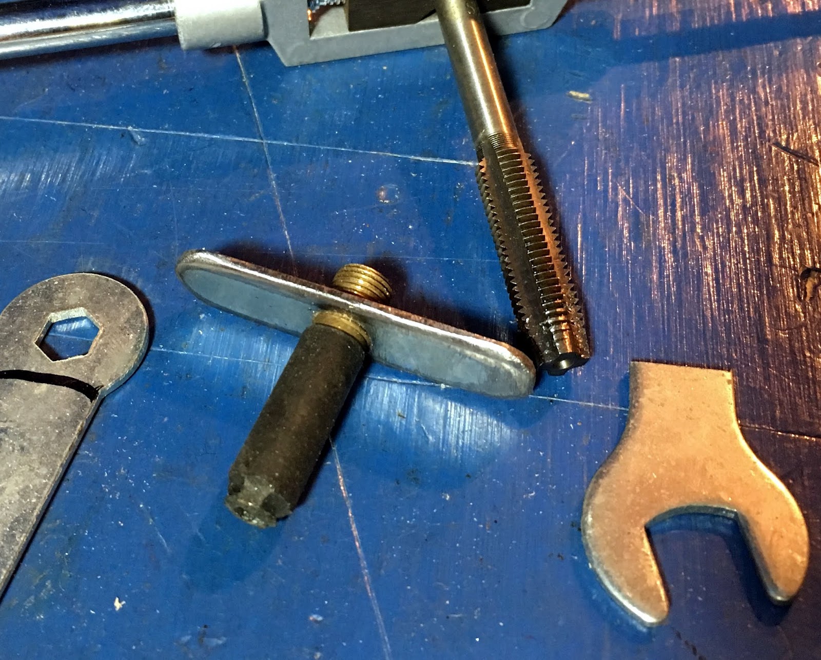
Here is how the parts were made:

As for the car itself - I planned on making a very elegant design, but being severely time constrained, had to resort to a basic rough bodywork made out of a block of wood:

In the end this design worked extremely well - it was very easy to operate and the car was about twice as fast as the next fastest car on the track :-). It could be made even faster with lighter car body and more aggressive angle of the CO2 cartridge, but this will require experimentation and time, which is in limited supply :-). The other thing to add would be an automatic start, instead of using manual start with vice grips. Perhaps next year...

Wednesday, March 16, 2016

CO2 powered pinewood derby car

In January my son participated in a Cub Scout Pinewood Derby Race. The official race has strict rules, such as the wight of the car must not be above 5 oz, the wheels may not be modified, the car itself must be made from the official block of wood provided by Boy Scouts of America car kit, the wheel axles must be from that kit, the car may not have any power, other than gravity, etc.

Parents in our Pack decided to have a no-rules race, except that the car must be safe for others and may not leave trace (smoke, fire, etc. are prohibited), but it must weight under 5 oz. This allows many forms of propulsion. I chose CO2 as the method (drawing inspiration from SpaceX and recent successful Falcon 9 landing). While my car was not quite as successful as Falcon 9, but hey, even SpaceX took 5 years before they had first valid launch!

It was a ton of fun designing and building the car (given my limited tools and materials choices). I must note that for this project I have not purchased a single piece of material - everything was already in garage in one form or another.

The overall project was half-success half-failure in terms of measured results, but it was a success that I enjoyed the process. Here is the video of the test runs of my no-rules car:
The build process was very involved and did not leave enough time for corrections, hence the project was not fully complete. Here is a gallery of images from the build process:
(click to see the album)
https://goo.gl/photos/TmptErtgLxDhSWiB8

Sunday, February 1, 2015

"Super flexible" TV wall mount for fitness room for $0

Last month I purchased a treadmill for my basement to be used by the whole family (guess who is really using it). We also have elliptical and stationary bike there. So we decided to put a smart TV on the wall. Since this is a new TV, it is the best one in the house and kids are often using it to play xbox. All of this requires me to be able to reposition TV on the wall depending on who is using it. The viewpoints are very different. Kids play xbox sitting on the floor, so the TV must be at their eye level on the left side of the room. When I run on treadmill the TV is pretty much against the ceiling on the right side of the room. When someone uses elliptical the TV needs to be in the middle of the room - centered between ceiling and the floor. Overall ===> this TV needs to be able to stay put on this wall anywhere from left to right wall, from the floor up to the ceiling. They do not sell mounts like this, so I decided to make one.

After some deliberation, I decided to use materials I already had from prior projects:
  • 10 foot long 1" diameter gas pipes (two of them) with a 2" threaded connector in between (I had used this to clean the rain drain under my driveway this summer and it has been sitting in garage ever since).
  • 16 feet metal cable - this was the cable I replaced when re-built garage door this past fall.
  • metal guide for the kitchen drawer (leftover from kitchen remodeling I did 10 years ago).
  • four mounting screws (whenever I throw away something big, I remove few good screws for future use and keep them in several jars of different sizes).
  • metal top from the old laundry washer machine (I replaced the mashine 2 years ago with a new one, but this metal sheet was too good to throw away, so I kept it - see picture below).

First - cut out the sheet of metal from the top of the old laundry washing machine (or use any other think metal and bent it properly:

 Once you complete the cut, make sure to file sharp sides of the entire piece to remove the edge. I filed it very nice so it is very smooth. Then mark holes to mount on TV by using a newspaper and then transferring the holes from newspaper into the metal and drilling those holes. The bent you see on the picture below is the one that was already on the piece and because it is a very think metal, it will hold the TV very well - there is absolutely no chance it will come undone - even if I put my own weight on it. You put your screws into the slots that are already on the back of your TV - these are the same slots you would use for any normal TV mount:
Since my basement room is wider than 10 feet and I did not want to purchase new pipes, I decided to connect two old gas pipes I already had suing threaded connector (see on the left pipe on the pic below). Make sure you screw it on very tight - as far as it gets. I use two pipe wrenches to make it super tight:
 Once you connect the pipes, measure the distance wall to wall and cut one of the pipes so that it fits wall to wall with about 1/8" gap between the pipe and the wall to allow for error and seasonal movement of wall:
Now is time to make brackets - these will be used to mount the pipe into the wall. I made mine from the kitchen drawer that was never used - cut the needed length and bent at 90 degree angle:

File all sharp edges from these brackets and drill two mounting holes in each. Now use stud finder to locate studs on your wall and attach brackets with 2.5" drywall screws to your studs on both sides of the wall.

Drill a hole thru the gas pipe and use a 2" bolt to attach the pipe to the bracket. Once you attach one side, you can mark the opposite side and drill a hole thru the bracket and thru the pipe so they align perfectly against each other - otherwise you can't run a bolt thru it - see below:
 The first part of the TV mount is done - now you can hang your TV near the ceiling height and move it left to right by sliding on the pipe. See picture below - despite the looks, this is unbelievably strong:
 This is what it looks like from the treadmill:
 I used black duct tape to wrap around the gas pipe (you can use any color you like to match your wall):

Here is how it looks when in use - but it is too high when kids play xbox while sitting on the floor (they move elliptical and bike to the back of the room):
Next step is not only to allow for sliding of TV between left and right walls, but to be able to lower it to the floor. This is trivial - simply attach the metal cable (you can buy 16 feet of cable at HomeDepot - I used leftover cable from garage door project - 20 year old cable is more than strong enough for TV). Attach this cable to the gas pipe - one long cable attached twice (only one end of the cable is shown below):
 Now - depending on how low or high you need your TV, wrap the cable one or more times around the "hook" as shown below and it will move the TV lower or higher on the wall - operation that takes only a minute - no screws, no mess. My kids do this easily and so far have not (yet) dropped the TV :-):
 Here is how TV looks when lowered almost down to the floor. The cable can easily move side to side and provides for a very solid connection.
The project took only about 2 hours to complete and cost me $0 as I already had all the parts in my garage. I would be interested to see other ideas on how to do this same thing - mount your TV on the wall so you can move it to any location you desire in less than 60 seconds.

Saturday, January 17, 2015

Pinewood Derby Car project

Today was Edward's first the first Pinewood Derby Car Race as a Cub Scout. We did this project together and had a ton of fun doing it. Before starting the design of the car, we watched a ton of youtube videos (such as this and many more) and rad bunch of articles on how to build a fast car and it all seemed very simple (and fun). I can't wait next year race - our CubScout Pack decided to have dad's car race the night before kids :-). Before I go into details - here is the final car we've had - it took 1st place in design as voted by scouts. as far as speed - well, it could have done better - and I will tell you why as I know what we will do next year :-).


According to "sources" the proper way to build a fast Pinewood Derby Car is to do these few things:

In our car we have implemented #1, #3 (kinda), #4, #5, #6. We did not do #2 as it was against the rules to modify the wheels and we did not do #7 because the rules prevented changes to the wheel base, etc. We also decided to sacrifice some of the #3 (aerodynamics) for the esthetics - mainly because we felt our car will be so fast, we can afford some drag :-).

First we decided what overall design we are going to have and together drew the shape of the future car on the paper:

Then we transferred the outline to the wooden block and made rough cuts with the large saw and then some finer cuts with the manual coping saw.


Then we used belt sander to smooth out the rough cut and shape the top of the car. This all was done in a matter of a few minutes - very easy.


Once we had the outline done, we used the Dremel tool with the sand paper attachment to make finer shape adjustments. This is a bit more delicate work and requires more precision.


 Nevertheless, Edward did some of this as well (mostly the bottom part of the car). This Dremel tool can easily ruin your design if you overdo it, but we passed this phase with only few minor mistakes.

The last part of the body work was to make a hole for the driver and cut our the rear spoiler and glue it onto the body of the car. These things are not very aerodynamic and were done on purpose - we traded of some speed for the "looks". However this is not what kept us from winning the speed race. More about it later (some drama, eh?). we made a windshield out of plastic box from grapes.

 The biggest thing in the Pinewood Derby car is the weight placement. We decided to make an opening in the rear to conceal all the weight - drilled the opening and made it all the way to the driver seat to that the bolt that will go in can also adjust the center of gravity if needed. Plus we can add or remove bolts to add or remove weight - and all of it will be concealed inside.

 To melt lead I closed one end of the copper pipe, filled it with led (from bb gun pellets - $2.5 per 5 oz box) and heated it with a torch. Then poured it into the opening in the car. The car almost caught on flames - the lead was so hot! We also kept the garage door open and wore face mask to avoid exposure to the lead fumes. Also use protective glasses to avoid potential splashes from hot lead into eyes. This is a risky part of the project, but it worked out very well.


Once lead cooled down, we covered it with about 1/8" of the epoxy glue so nobody will touch the lead and we can sand and pain it. Then I drilled a hole all the way to the driver seat - this is where the bolt for weight and gravity center adjustment will go.

Our center of gravity was 3/4 of an inch in front of rear axle. This is good for smooth track, but may not be great for the track with small bumps as at high speed you can pop front wheels and go off the track. This is why having long hole as shown below is so useful - by using a screw driver I can move the bolt deeper into the car in a matter of seconds without changing the weight of the car, but this can shift my center of gravity in either direction.

BTW - the thread marks you see in the picture below are made by simply drilling the right hole first and then screwing the bolt into it - lead is very soft and bolt makes its own thread.

Once all structural work was done we primed the car twice - with sanding of the first layer.


 And finally painted it once with gold paint and then drew numbers and letters on the car. Next day we painted it once with polyurethane. Once it was all dry we used car wax for extra polish.

Now it is time to work on wheels. First we worked on polishing the nails. First - put it in the drill and apply file while spinning the nail. After that use sand paper to smooth it out and finally use polishing compound. Once you get the hang of it, it takes less then 10 minutes to polish a nail to mirror finish.
 Since we wanted to ride on canted wheels - we had to bend nails to about 2 degree angle. Instead of buying a $100 device to do it, I made my own device from a 2x4" stud. Just make two wide cuts with a regular saw - each cut perpendicular to another, then insert polished nail with its head into one of the slots - with the sharp side of the nail protruding outside of the block of wood by the lenght of the section that needs to be bent. Then tap with a hammer on that protruding part of the nail. Not very precise, but cheap and easy.
 The benefit of this approach of bending the nail - vs. holding it with pliers is that soft wood does not scratch polished surface of the nail. And you must bend it after you polish it - you can only polish straight nail. And once you bend it - if you scratch it - you better start with a new nail as polishing bent nail is nearly impossible.
 Finally - we polished the sides with graphite, added bunch of graphite into wheels and on nails.
We raised one front wheel so it was about 1/16" above the ground. Before we glued the wheels, we inserted nails and ran tests on the floor to make sure our car does understeering for about 2" over 4 feet - this is for rail riding. And this is where we made a big mistake! Later on when I did test runs on the track, I saw how this rail riding slows down the car. I do not think next year we are doing rail riding and will make straight rider. After all wheel alignments were done, we use epoxy glue to attach nails.
 I did not mention, but along every step above, we were constantly weighting the car - so that we would know how much lead to use, what is the impact of paint, nails, wheels and other things on the weight. The point was to build a car that would be 2 or 3 oz lighter than the regulation 5 oz weight and then cut small bolts into short segments (and cut the slot for screw driver). We had about 7 cuts of this bolt of different length (and weight) so we have a choice when getting as close to 5 oz as possible.

These bolt' segments serve 2 purposes. One is to add or remove weight (the race scale can be different from the one we used at home) and Two is to shift center of gravity towards the front or rear as needed - depending how front wheel behave (you do not want those front wheels to pop on a bump). This resulted in our center of gravity being 3/4" in front of the rear wheels. Very fast design.

The entire project took about 10 hours and was ton of fun. We did win the #1 place in design, but were in the middle overall on speed. After the race was over, I did several test runs on the track and it became VERY obvious that our rail riding was slowing the car down by A LOT. It was very easy to spot - I wish we had access to the track when we were doing the tests (before gluing nails to the body). This was a trivial error to avoid, but we did not know simply by not test riding on the track.

The biggest lesson of this is that if we want to win on speed, we need to do test rides on a track. Otherwise it is a gamble and only experimentation can complete the project. The funny thing is that all of the design and construction is 99% of the effort in the project while test riding and adjusting it on the track is 1% of the effort, but it is very critical to achieve high speed.


What will I do differently next year?

  1. Next year I will avoid rail riding and adjust the wheels so that car rides straight line.
  2. I will bend nails half the amount of what I did this year (probably about 1 degree)
  3. While polishing nails, I will use sandpaper up to 1500 grit (see this article for details)
  4. Pack the wheels densely with graphite and do not run the car after that.
  5. Make shape totally aerodynamic for maximum speed (and make fancy shape on a separate car - for dad's race)
  6. Possibly make three different cars with slightly different designs and have them compete in my garage to deserve the race?
  7. Make my own short track out of wood and cut grooves with rotary tool - and test test test the car!
Here is the concept car design for the 2016 race - we plan on making a wind tunnel to test aerodynamics and short test track to make sure it rides fast.